Introduction:
The most sophisticated cases, besides having front USB ports, also have plugs for microphone (mic in) and loudspeakers (or ear phones), a feature makes installing a microphone or ear phones in a PC very easy, since we don't need to take the case and look for a place into which install such peripherals (or even loudspeakers).
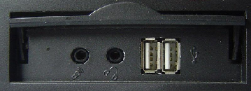
Detail of case with front USB ports and on-board audio jacks.
To use those plugs, your motherboard needs to have an integrated sound card (in other words, on-board sound). The installation, however, it is not as simple as it seems, and we will explain in today's column how it has to be done.
A group of seven wires leaves the plugs. At the end of each wire there is a small black connector, and, in this connector, we can read the function of the wire. You will find the following wires: Mic In (or Mic Data), Ret L, Ret R, L Out (or Ear L), R Out (or Ear R) and two Gnd (or Ground). If you watch carefully, the Ret L and L Out wires are connected to each other, the same happens between the Ret R and R Out wires. If your case also has an input plug (line in), there will be two other wires: Line In L and Line In R.
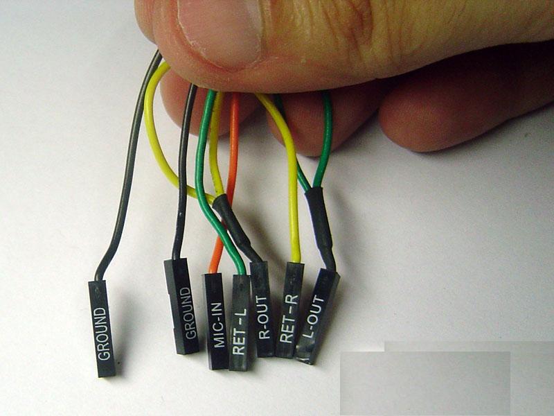
Wires of the front plugs of the case.
You have to look for the place of installation of such wires in your motherboard. This place is indicated as Audio, External Audio, Ext Audio, Front Audio, F Audio, or something like that. This place consists of a 9-pin connector, and there are two jumpers installed, making the connection of some of these pins. The exact position of this connector varies depending on the motherboard model, and you will need its manual to precisely locate it.
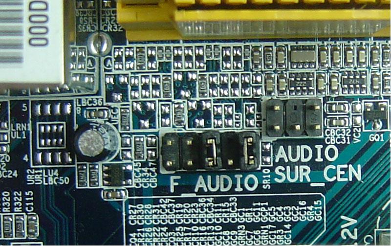
Place on the motherboard where the case wires have to be installed.
To install the wires, the first step is to understand the pin numbering system of the motherboard connector. There are nine pins in the connector, but the connector is considered a 10-pin one because one of the pins was removed (pin 8). The jumpers connect pins 5 and 6 and 9 and 10. As there is the space without a pin (pin 8), it is easy to discover the numbering of the other pins. Notice that the pins are oddly numbered to one side of the connector (1 to 9) and evenly numbered to the other (2 to 10).
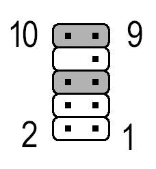
Motherboard audio header pin-out.
Remove the jumpers. The connection of the wires must be made the following way: Mic In to pin 1; Gnd to pins 2 and 3; R Out to pin 5; Ret R to pin 6; L Out to pin 9, and Ret L to pin 10.